Sadly the Arduino based prototype for the stairway lighting project just didn’t stand up to the 7th Commandment, that of 99.99% reliability!
No matter what I tried, I just couldn’t get the networking side stable enough to ensure it worked all the time and it would occasionally fail to light the stairs 🙁 I also had some reservations about where I was going to mount the enclosure and how I was going to get networking to it too. I did briefly consider moving from ethernet to Wifi, but that would have involved purchasing a Wifi shield which are quite costly!
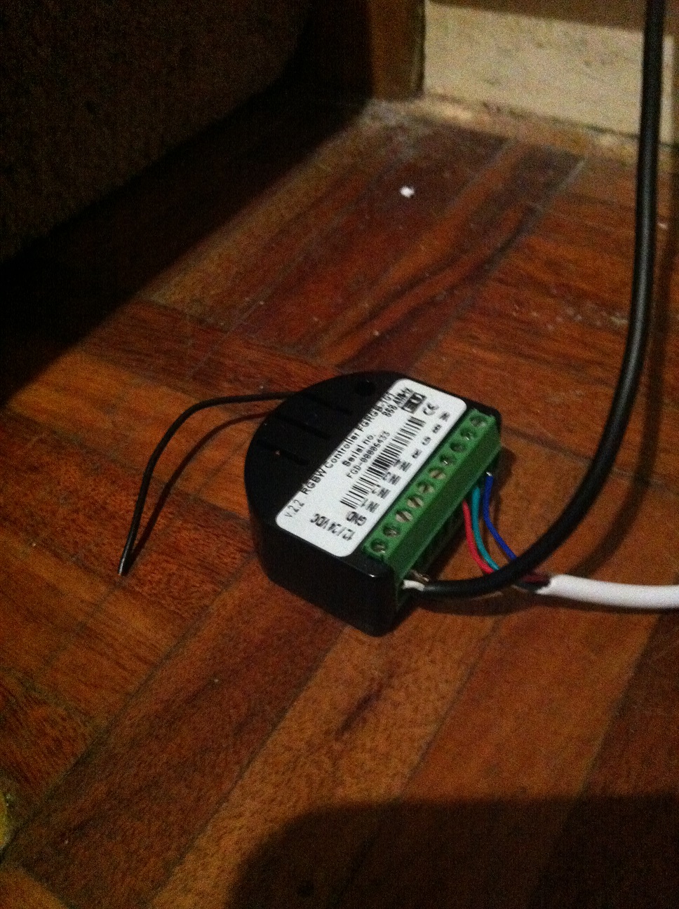
Fortunately when I began this project I’d picked up a Fibaro Z-Wave RGBW Controller for the spares cupboard as one of the possible options. I’d discounted it in favour of the Arduino approach as I liked the idea of using the WS2801 RGB LEDs as they were individually addressable and you could make funky patterns with them. But now this project had been dragging on a bit and was in need of finishing off, so simplifying things somewhat would help!
So I cracked open the wrapper on the Fibaro module and rigged it up with a test length of RGB LED strip – fortunately I had some of the “Common +” type in the spares cupboard already, so no need to purchase any more!
I’d have really preferred to use some full four channel RGBW LED strip, but these still seem to be excessively expensive in the UK – the cheapest I found were some 24V strips and together with the PSU it was going to be nearly £200! So I’ll make do with the RGB LED strip that I already have!
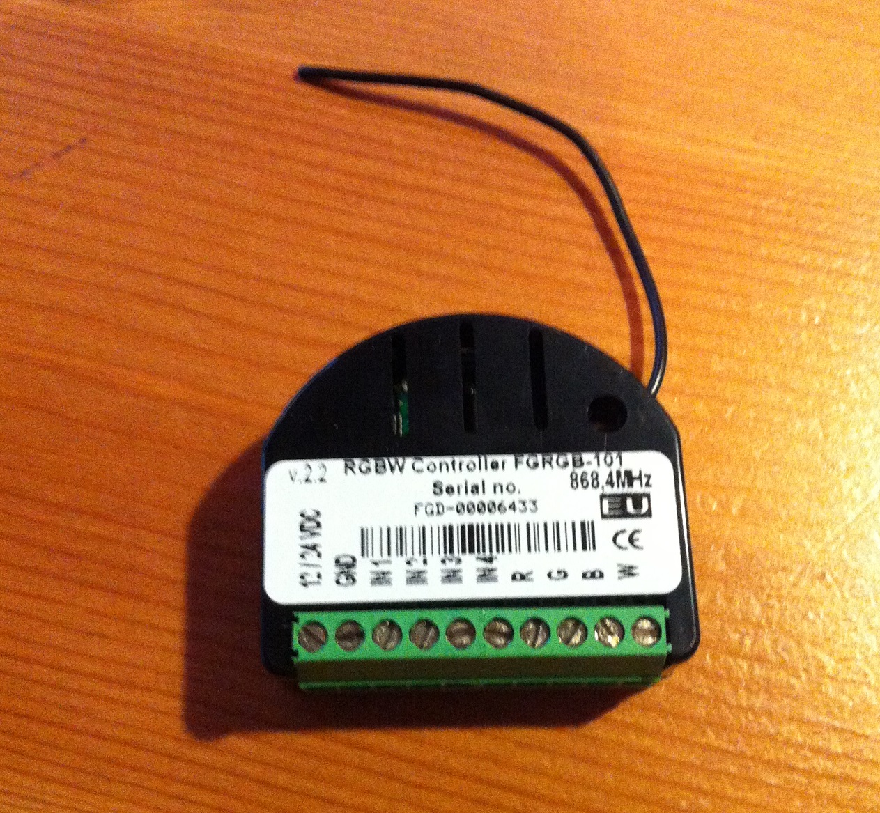
Once it was wired to the LED strip, I connected it up to a temporary 12V 5A power supply – I figured it probably needed something quite beefy, I guesstimated at about an Amp per metre.
Next it needed to be included in my Z-Wave network – this is a simple process carried out on my Z-Wave controller of choice, in this case a MiCasaVerde Vera 2. My Vera is in the loft and I’ve never needed to do any of the “take your Vera to the device” or “take the device to Vera” nonsense, I’ve always just carried out a “full-power include” or “full-power exclude” and never once has Vera failed to find the device. We have reasonably large house too, 4 bedroom detached with garage and big garden – Vera has always managed ok!
Straight after inclusion and the customary “reloading” of the LUA engine, Vera was showing 6 additional devices in the UI:
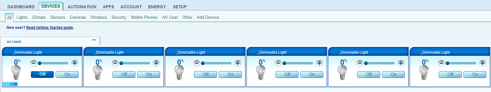
A quick bit of experimentation was required to identify what each device was controlling, after which I could label them appropriately:

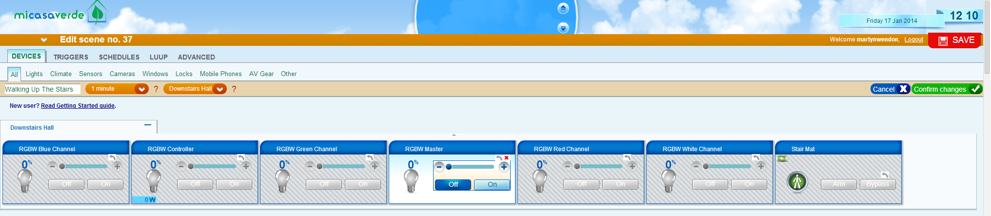
Essentially there’s a device per RGBW channel and a “master” that controls all the channels on / off and dim. There’s also a “parent” device that shows the power consumption being used.
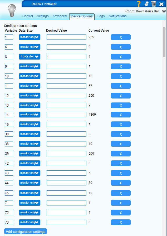
With Fibaro modules there’s usually a bunch of configuration options, in Vera these are known as “parameters”. I usually add them all into the “Device Options” tab for the device as “Monitor Only” as this lets me see how they are configured by default and easily change any that I may need to tweak:
I played around with it for a while – each “dimmer” control on the Vera UI changed the colour of each RGBW channel. The dimmers only move in 10% increments on the UI so it was a bit difficult getting accurate colours. You can set finer percentages in LUA though if that level of control is needed. Unfortunately at the moment in Vera there’s no “colour wheel” functionality, unlike in the Fibaro Home Center 2.
There were some oddities like when turning off using the Master device the Controller device stayed showing 100%:

Or when turning off from the Controller, the Master device AND the White Channel stayed showing 100%:
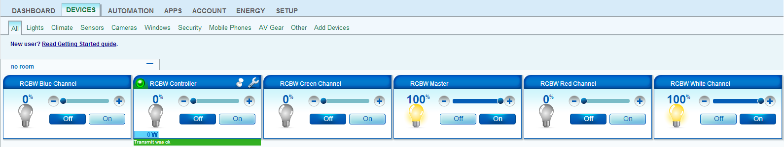
I’m not sure what was causing that, it might have been due to not having anything connected to the White channel, or might be a bug with the Vera implementation.
Weirdly the “Controller” and “Master” devices in the Vera UI seemed to track the percentage level that was highest on the four colour channels:

Since I now had both the “output” (the RGBW Controller) and the “input” (the Stair Pressure Mats) in Vera, I decided to implement the Home Automation logic in Vera too, rather than going the convoluted route of Vera -> xAP -> xAP Floorplan -> HTTP -> Vera. This is an approach that I’ve been taking more and more during the past year or so, as I migrate much of my older legacy HA systems across to Z-Wave. The Vera really is a very capable Home Automation controller and through the addition of various “plugins” can also integrate other technologies!
As I wanted to crack on with the physical install, which I’ll get to in a bit, I decided to just implement some simple logic for now based on somebody going up the stairs and somebody going down the stairs. Most logic in Vera is handled through the designing of “Scenes” so that’s where I started:

My kids chose a suitably garish colour for the LEDs and this was simply a case of setting each of the dimmers appropriately. You’ll notice that the timing for this “phase” of the Scene is “Immediate”, this means anything selected here will happen as soon as the Scene starts. Talking of which, I set a “Trigger” for the Scene as follows:
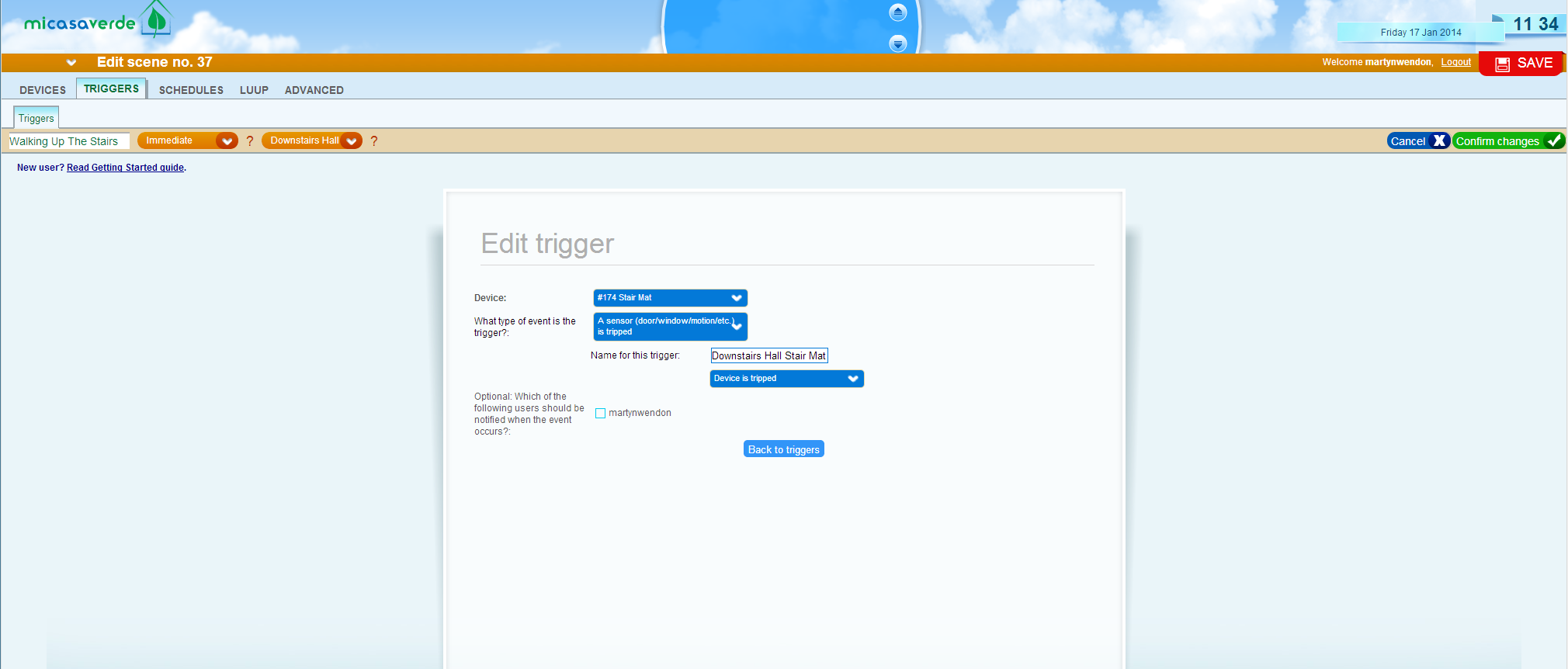
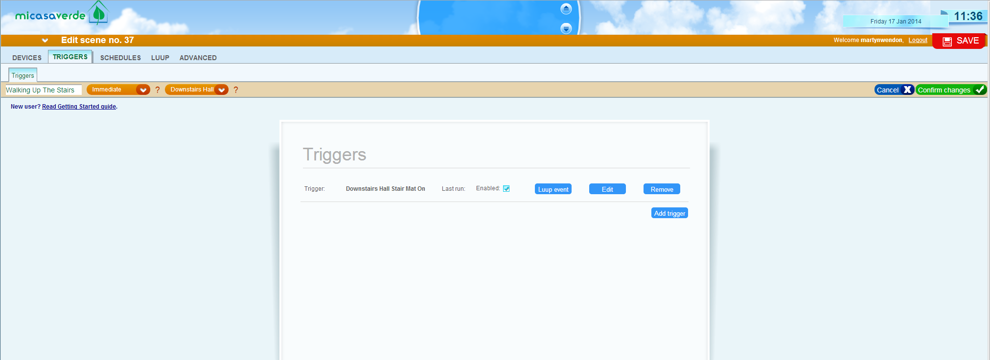
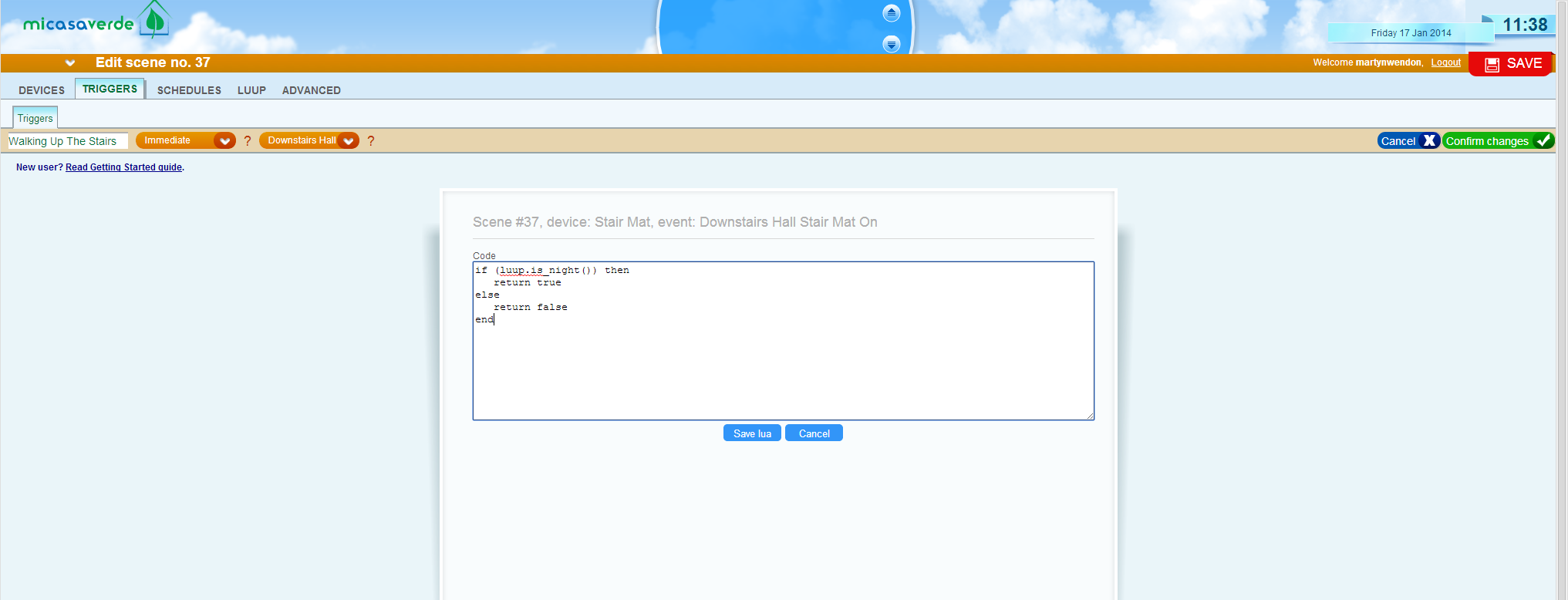
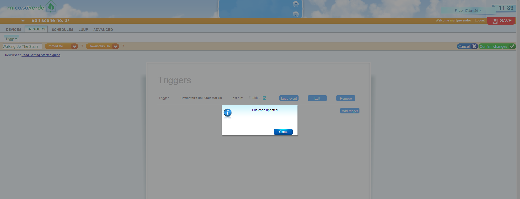
Pretty simple really! When the downstairs “Stair Mat” device is tripped, the Scene will start. You’ll recall previously that the stair pressure mats are hooked up to Fibaro Universal Door & Window Sensors. Once the Trigger was added, I needed to add a condition to it so that it only ran “at night”. This is done by adding a “Luup event”:
There’s a wealth of information on LUA and LUUP a the MiCasaVerde Wiki and for more in depth LUA coding I use ZeroBrane Studio which is just awesome! For this particular scenario, a few lines of LUA were enough:
To turn the LED lights off again, I simply added a 1 minute delay phase to the Scene:

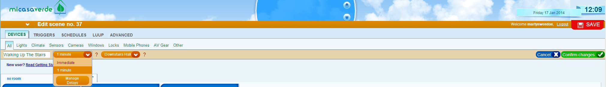
Then set the Master device to turn off:
I created an identical Scene that was triggered by the upstairs stair pressure mat to complete the logic.
Once this project is finally finished I’ll tweak the logic to add functionality such as a timer restart so that the LED lights won’t turn off until 1 minute has passed since either stair mat was triggered. I’ll likely also remove the “is_night” check and make the lighting dependent on actual light level – this should be fairly simple to do once I get round to installing my Aeon Labs 4in1 Sensors in the upstairs and downstairs hallways!
So that’s the software side taken care of, now I needed to get on with finishing the hardware side of things! First up was saying goodbye to the temporary lash-up I used for testing the Arduino prototype, this was quick enough to do as I’d only been using tie-wraps to experiment with the positioning of the LED strips.
During those experiments, I’d decided that the LED strips would actually look better installed along the wall along the “Stringer” in some kind of channelling. The problem I’d come up against was finding a way to mount the LED strips that looked neat and tidy – I didn’t just want to stick them on! I played around with some plastic conduit and some wooden batten with a groove cut in it, but both of those ideas looked clunky 🙁
Searching on Google I discovered that you could actually buy extruded aluminium channelling specifically made for mounting LED strips, so a quick bit of eBaying later and I had 5 metres worth on order. Ok, ok, the budget for this project is creeping up, but fortunately I’d sold some legacy HA equipment on eBay a few days before, so it was kind of self-funded 🙂
While I waited for the channelling to arrive, I took care of the power requirements. The ideal location for the Fibaro RGBW Controller was going to be at the bottom of the stairs. There used to be a single power socket there, but I disconnected it a few years ago after discovering that it wasn’t wired in particularly safely by the previous owner of the house. I decided to re-use that location but do the job properly – I removed the single socket and replaced it with a double:
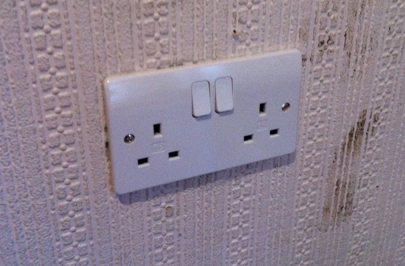
Yes, I know that the wall needs cleaning! Fortunately on the other side of this wall is the garage which I re-wired several years ago and runs off of it’s own Consumer Unit. It was therefore easy for me to add a branch to an existing 20A radial run. I chose to add some additional protection by fitting a neon lighted double pole fused spur and down-rated the fuse to 5A. The socket has also been labelled clearly since taking the above photograph so anybody in the future will know where it is powered from and what it is rated for!
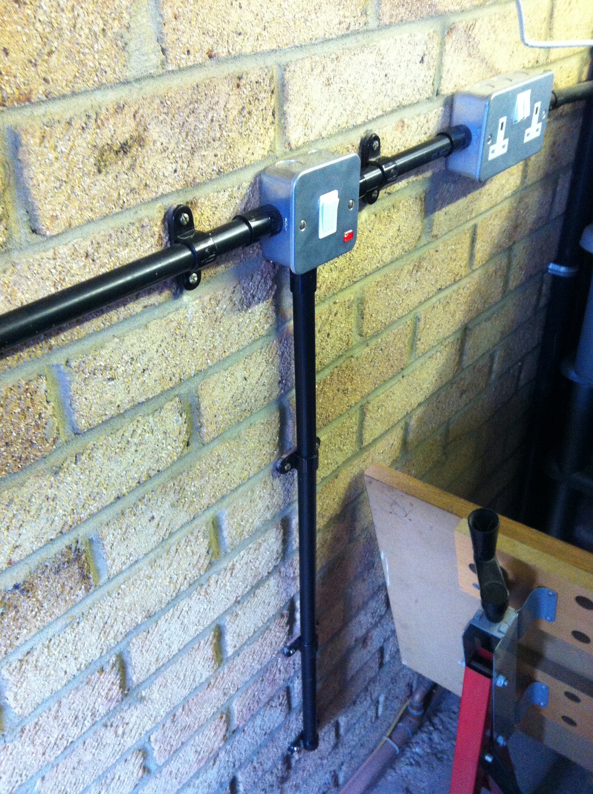
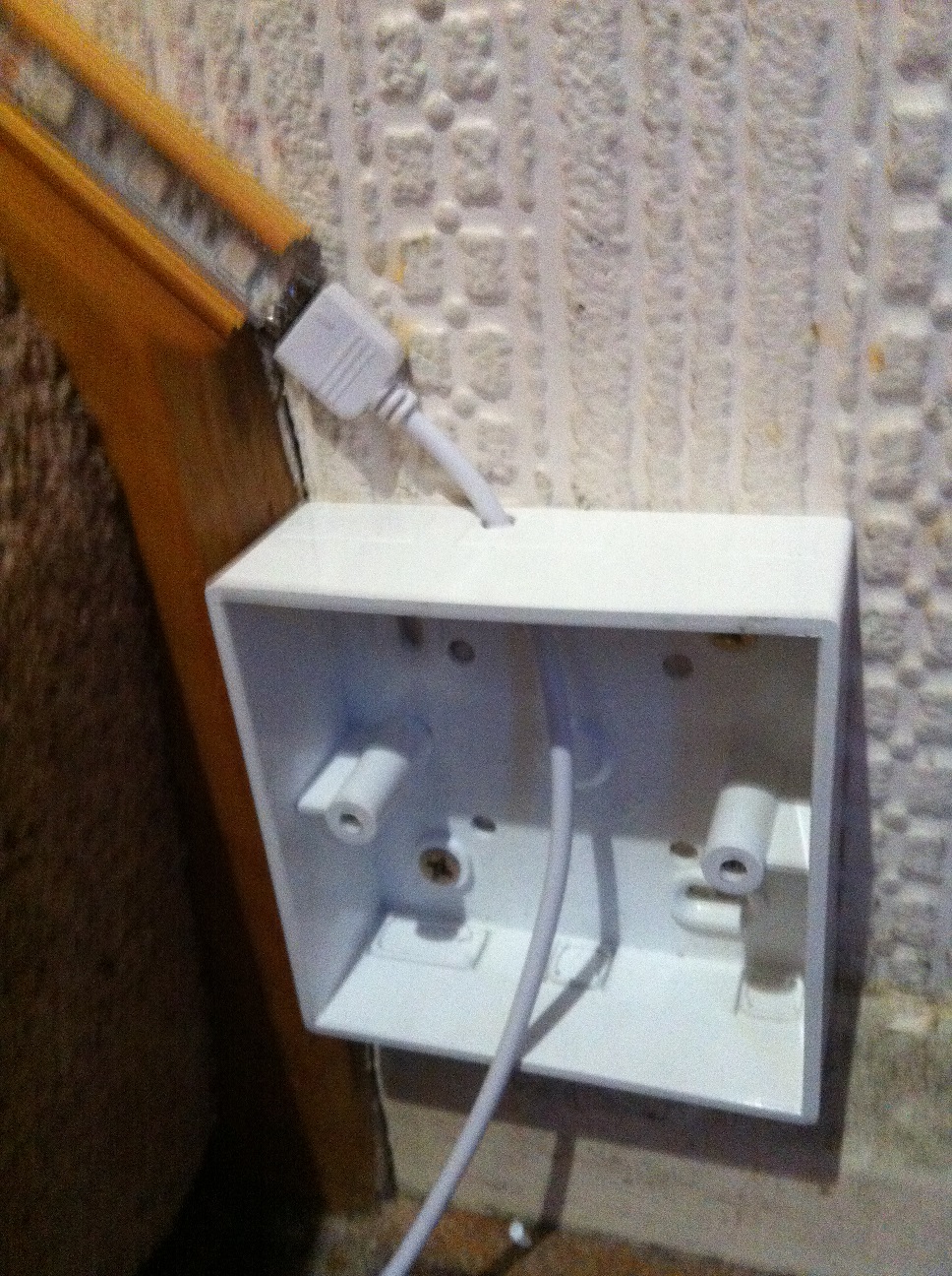
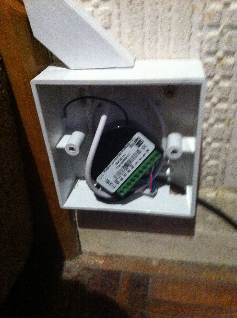
While I had the tools out I also fitted a surface mount box and faceplate to house the Fibaro RGBW Controller. I decided to surface mount it as if I’d flush mounted it it would have been difficult to get the power supply into it – since this was being provided by an external wall-mounted 12V PSU.
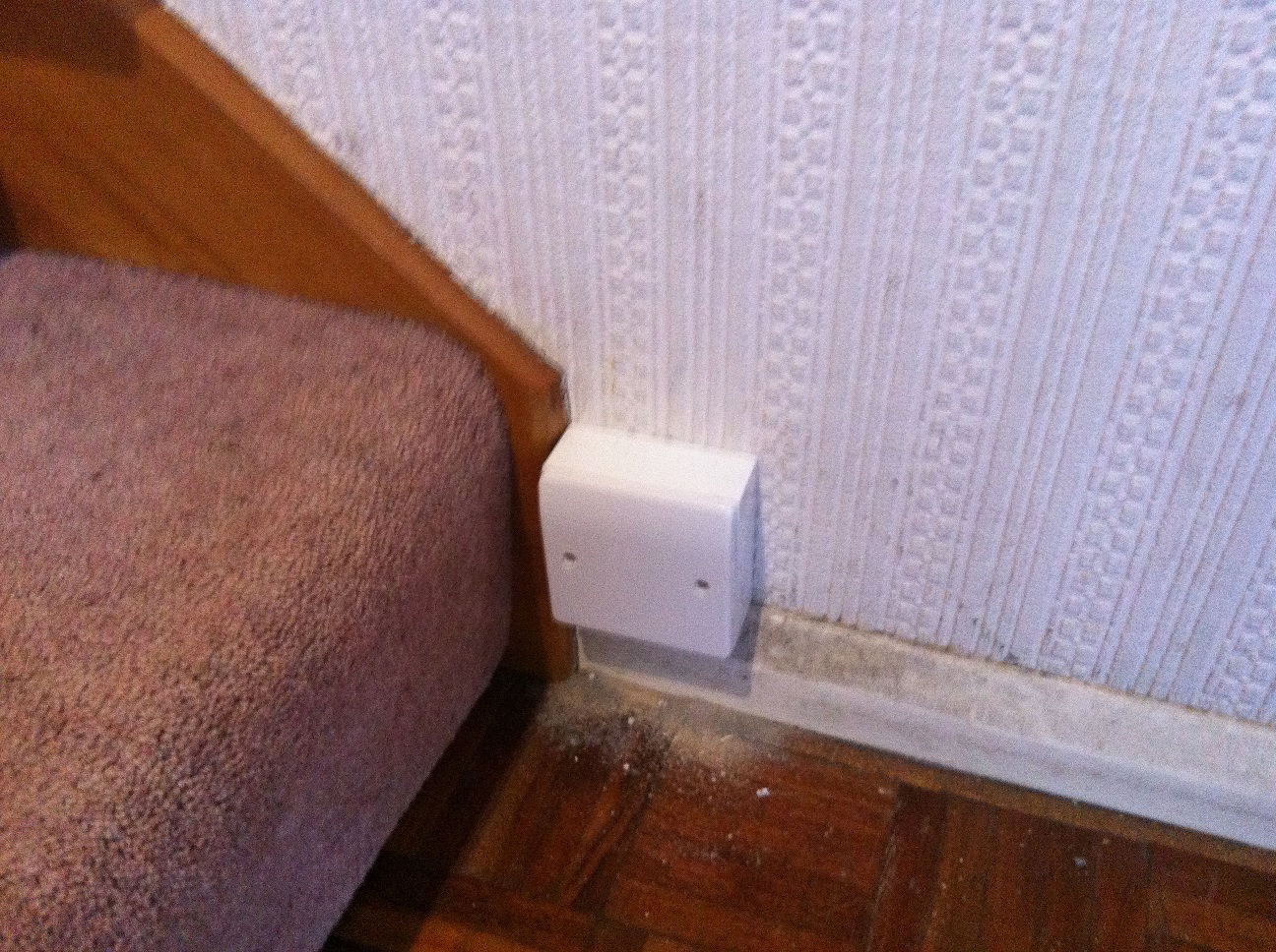
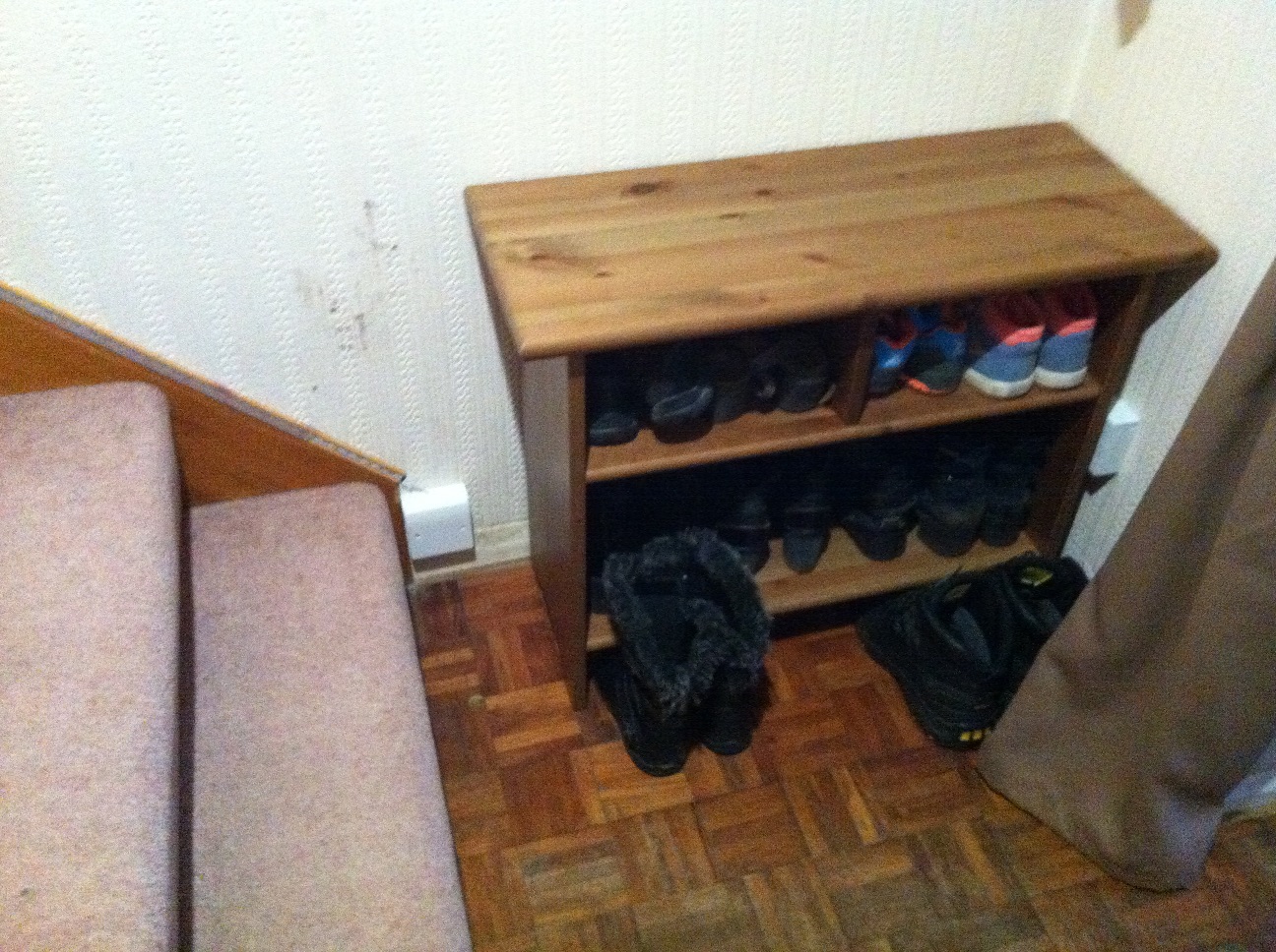
There’s actually a shoe rack that goes in this part of the hallway, so it won’t stand out too much anyway! A few days later and the aluminium channelling arrived, it was a simple job to install that:
This stuff is pretty cool, it’s made really well and the LED strips fit nice and snug in the channel. It comes with end caps too and I chose a slightly diffused cover to take off some of the glare from the LEDs.

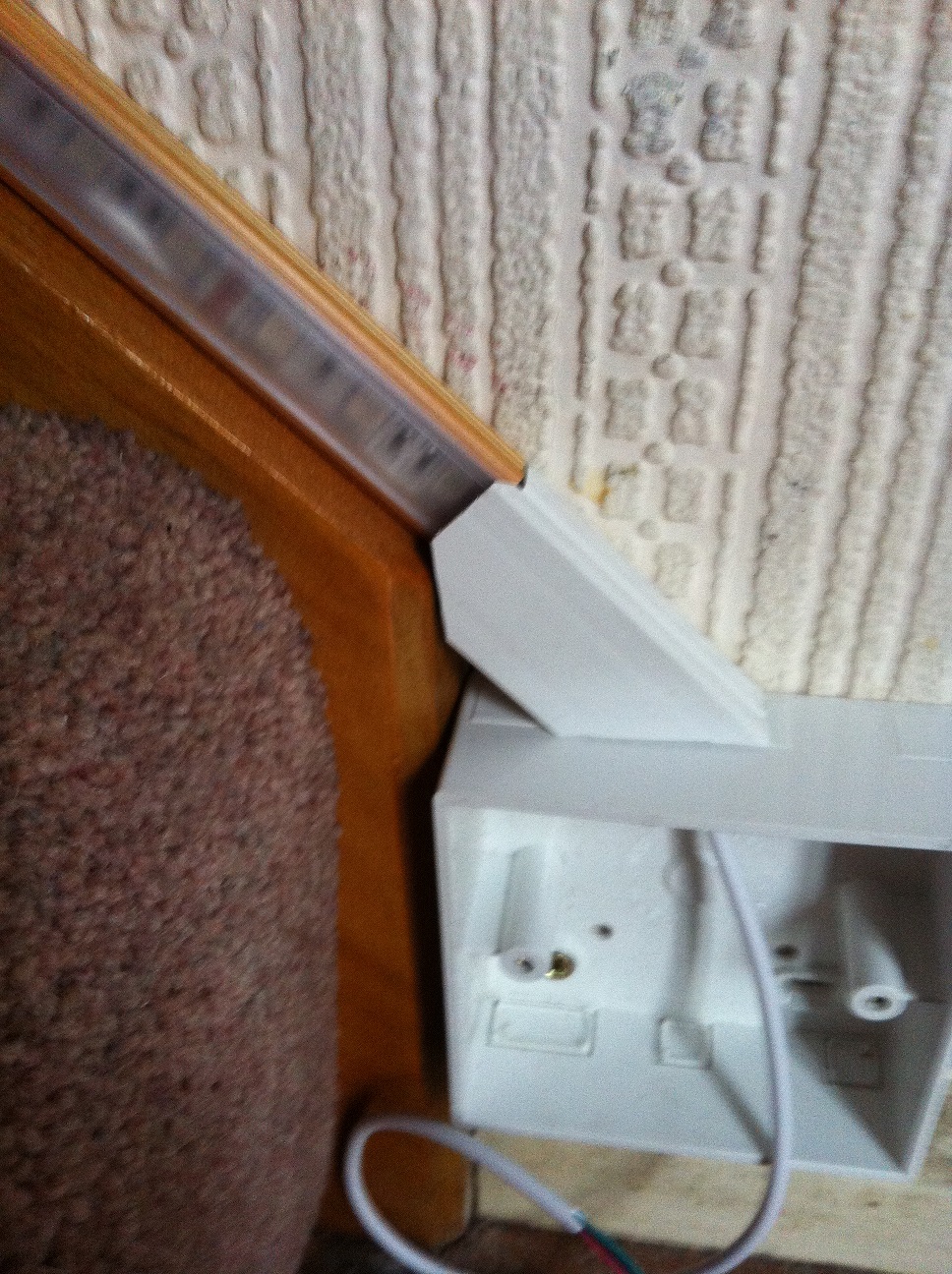
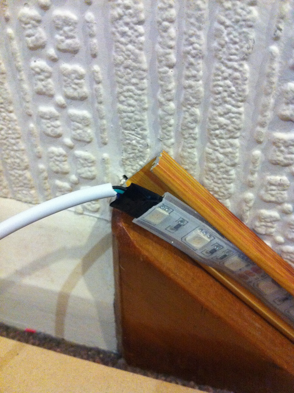
Next up was sorting out the wiring – I decided that I wanted to make this end of the LED strip “un-plugable” rather than being permanently connected, to make it easier for maintenance.
It didn’t feel right leaving that fragile connection exposed, so I added a small piece of trunking to cover and protect it. Once it’s had a bit of white silicon added it will blend in nicely.
Next up was wiring the module to the LED strip and to a power supply. Again, pretty simple stuff! The PSU that I’m going to be using is wall mounted, so I will run the small low voltage cable along the skirting and the PSU itself will be hidden behind the aforementioned shoe rack.

All in all I think it looks fairly neat and once the shoe rack was in place everything blends in to the background quite nicely. OK, I’m cheating slightly with the photograph below as it was from earlier in the installation, but you get the idea!
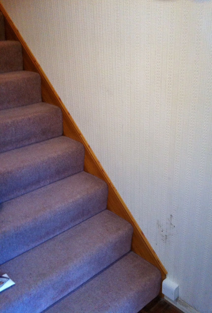
Just a few more things to take care of now. At the top of the stairs where there is a small landing followed by a further two steps and I’d already decided in my previous experiments with positioning of the LED strips that I wanted to “turn the corner” and go right the way to the top of the stairs. This meant I needed to extend the LED strip with some cabling under the carpet to connect to the final piece of LED strip at the top of the stairs.
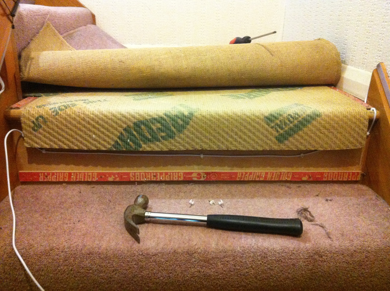
I tried a couple of different approaches to this and settled on the following. First up was soldering on the extension cable, this was quite tricky to do “in place” and took longer than it should have!
Tacking the cable down and running it under the carpet was easier thankfully!
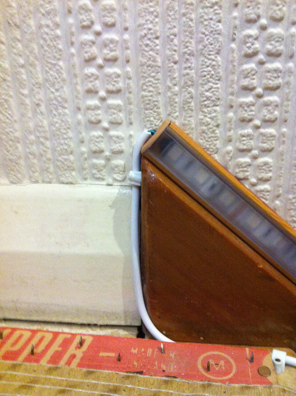
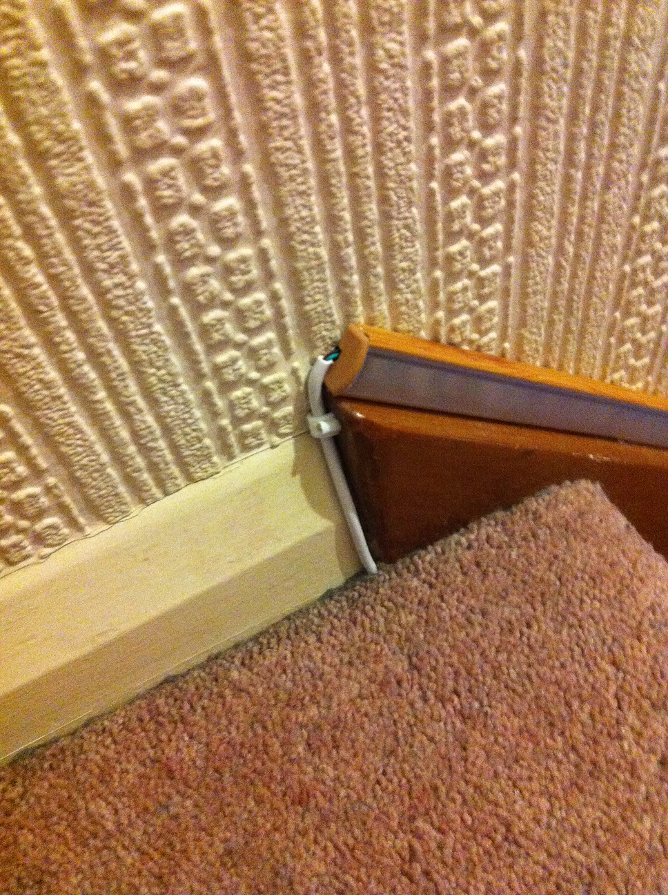
It looks fairly neat once the carpet is back down and after some touching up with a white silicon gun will sort out the slightly exposed wiring.
Running the extension cable under the carpet was pretty simple too, I chose the path of least resistance!
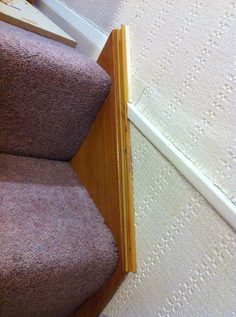
When installing the small piece of aluminium channelling on the stringer of the last two steps, I discovered a small problem stemming from yet more shoddy workmanship. This time though the previous house owner wasn’t to blame, it looks like this was from when the house was actually built.
It seems that where the wall of the first floor meets the wall of the ground floor, a protrusion of the first floor flooring has been left, likely to try and disguise the fact that the walls don’t line up very well 🙁
So I had to fit a small piece of infill wood – it’s not exactly my finest work, but it will do for now and once it’s been filled and painted it won’t stand out too much!
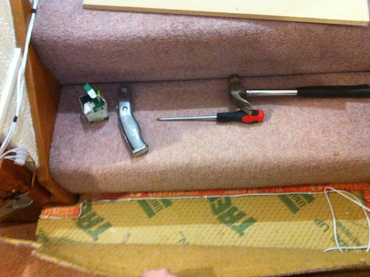
I learned my lesson with the previous soldering exercise and decided to solder the extension cable on with the LED strip “free” of the channelling:
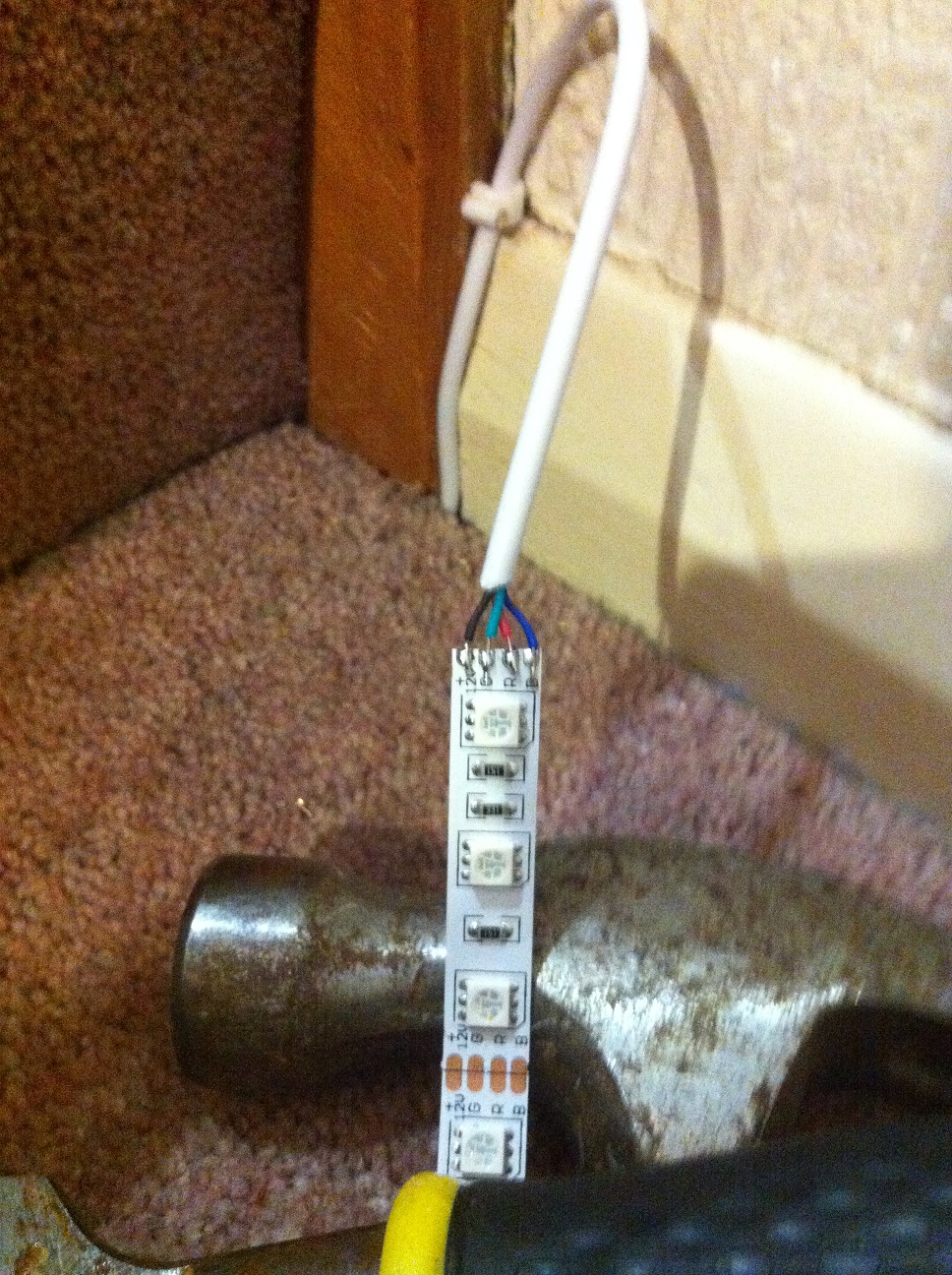
The LED strip was a tight fit getting in this time, unfortunately the channelling was a touch too short. Although it was measured to fit the length of the stair stringer, I’d forgotten that the LEDs can only be cut every 3, so it took a bit of effort cram them in. They look a bit “wavy” in the following picture:
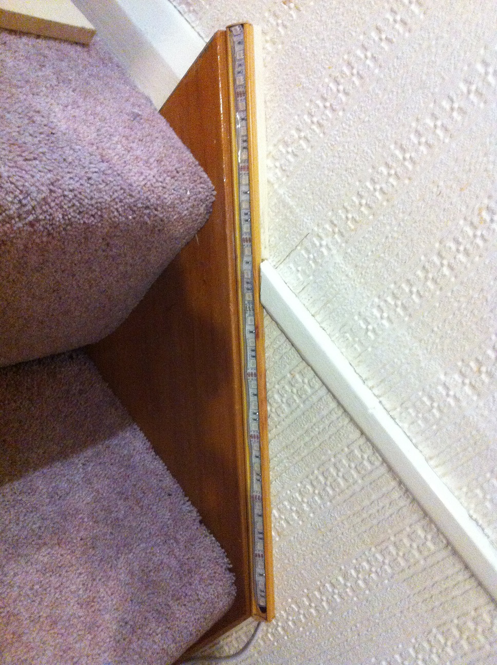
But once the cable was tacked away and the cover was put on the channelling, it doesn’t look too bad!

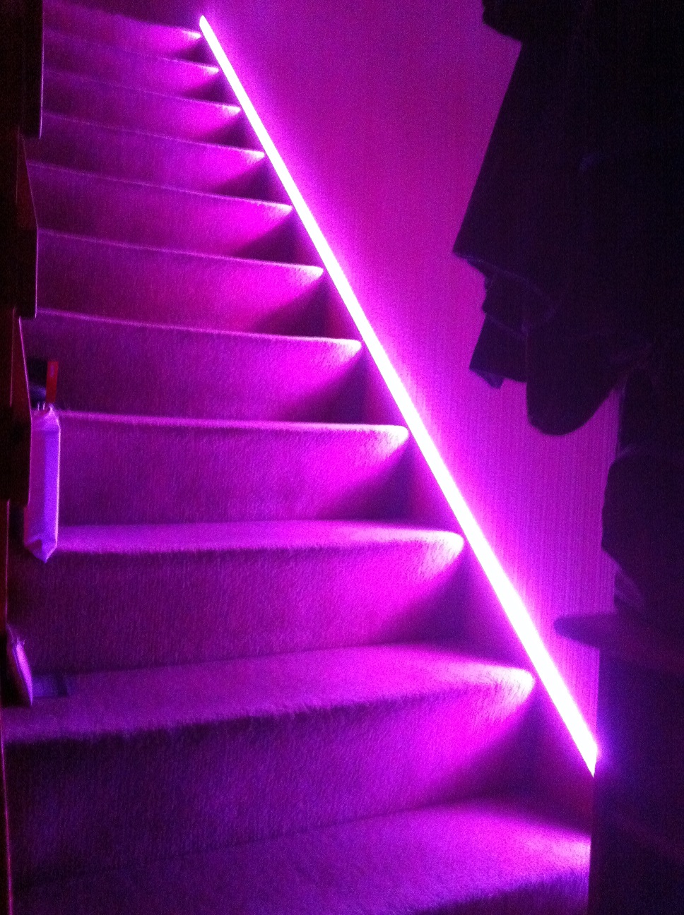
And that’s pretty much it! Job done – finally!
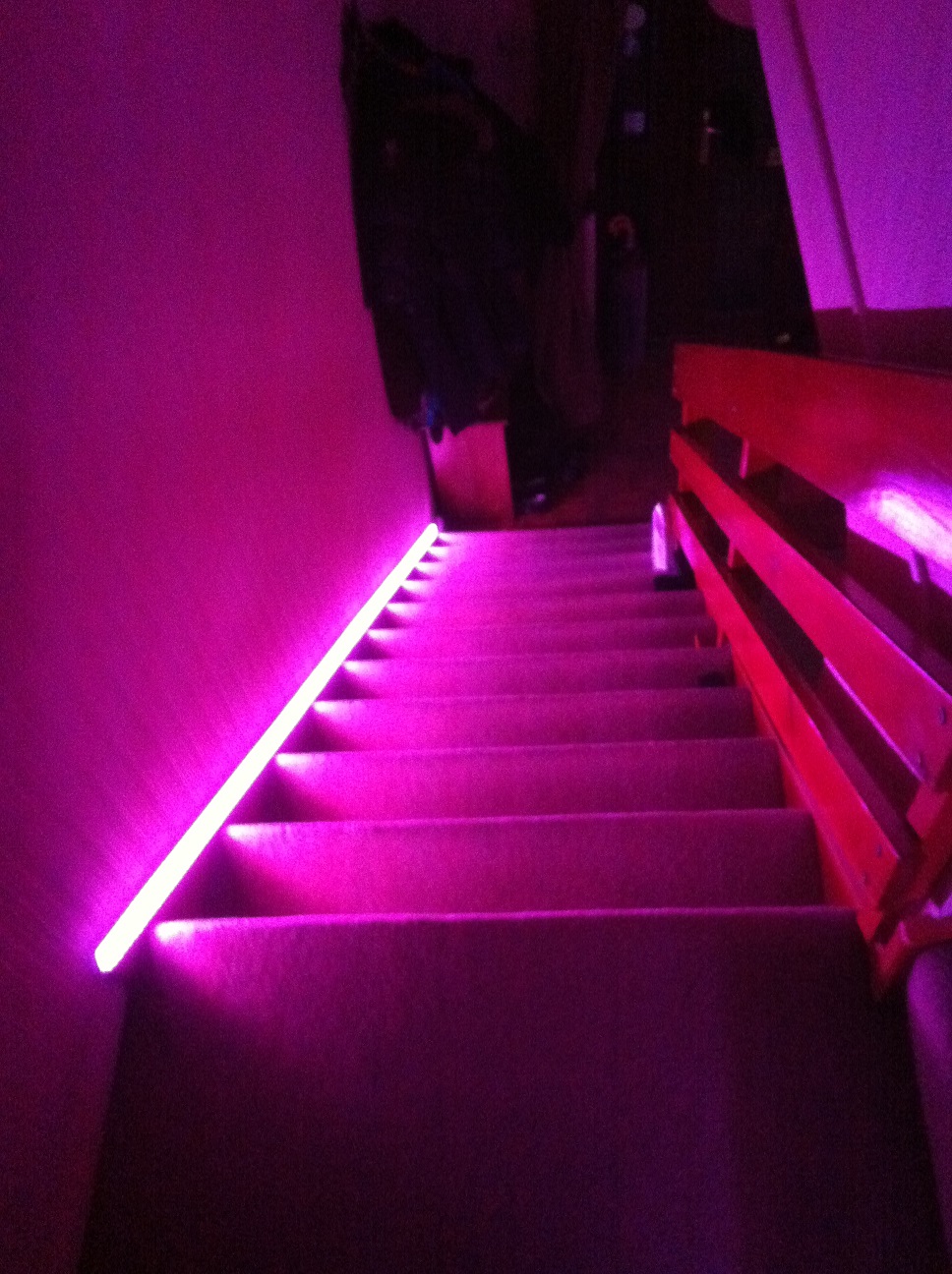
This project has taken quite a while and has gone through a number of changes along the way, but I think the final result is pretty good. The original “problem” has been solved and we now have some funky coloured lighting too. It’s energy efficient, since the strip only uses a few Watts and through the Scenes on the Vera it only comes on when it’s needed for a minute at a time.
Here’s some photos of the lighting in action:


Thanks for reading,
Martyn Wendon